𝗥𝗲𝗱𝘂𝗰𝗶𝗻𝗴 𝗛𝗮𝗻𝗱𝗼𝘃𝗲𝗿 𝗜𝗻𝘁𝗲𝗿𝗿𝘂𝗽𝘁𝗶𝗼𝗻 𝗶𝗻 𝟱𝗚 𝗔𝗱𝘃𝗮𝗻𝗰𝗲𝗱

Challenge:
New and emerging extended reality (XR) and time-critical communication (TCC) use cases require a significant reduction in handover interruption time. This also benefits delay-sensitive smartphone apps.
Solution: Layer 1/Layer 2 (L1/L2) Triggered Mobility (LTM) in 5G Advanced. This Speeds up the handover procedure. •Reduces interruption in data transmission and reception.
what is LTM Mechanism:
Pre-configures User Equipment (UE) with a handover command for an LTM candidate cell and triggers the switch with lower layer signaling.
Advantage: Allows early downlink (DL) and uplink (UL) synchronization before the cell switch, speeding up target cell access.
Future: LTM is being implemented in 5G Advanced networks and UE chipsets and is expected to be foundational for 6G mobility
Handover in Mobile Systems - An Overview
Purpose of Handover:
Ensure UE is always connected to the cell with the best signal quality.
Goal: Handover from source to target cell as quickly as possible with minimal interruption.
Current 5G (L3 Handover):
Source base station (gNB) sends a handover command (RRC message - Layer 3) to UE.
Interruption: 50-90ms in a well-tuned network.
5G Beam Management:
Handles UE movement across different beams in the same cell, especially in higher frequency bands. •Interruption: Few milliseconds due to lower-layer signaling.
Limitations of L3 Handover for TCC:
Interruption is too large for TCC and XR.
Previous Attempts & Limitations: •Dual Active Protocol Stack (DAPS): Difficult to implement, significant limitations. •Conditional Handover (CHO): Reduces handover failure risk by providing configurations for potential target cells. •Inter-cell Beam Management: Short interruption but cumbersome over larger areas as it operates without RRC reconfigurations.
LTM's Advantage: Extends inter-cell beam management to handle RRC reconfigurations, combining multiple-candidate configurations (like CHO) with efficient signaling.
LTM L1/L2 Triggered Mobility - How it Works
Core Principle:
Network triggers handover via L2 signaling, relying on L1 measurements from the UE.
Benefits:
Faster handover, pre-synchronization with LTM candidate cell (target cell), reduced execution time, signaling overhead, and connectivity interruption.
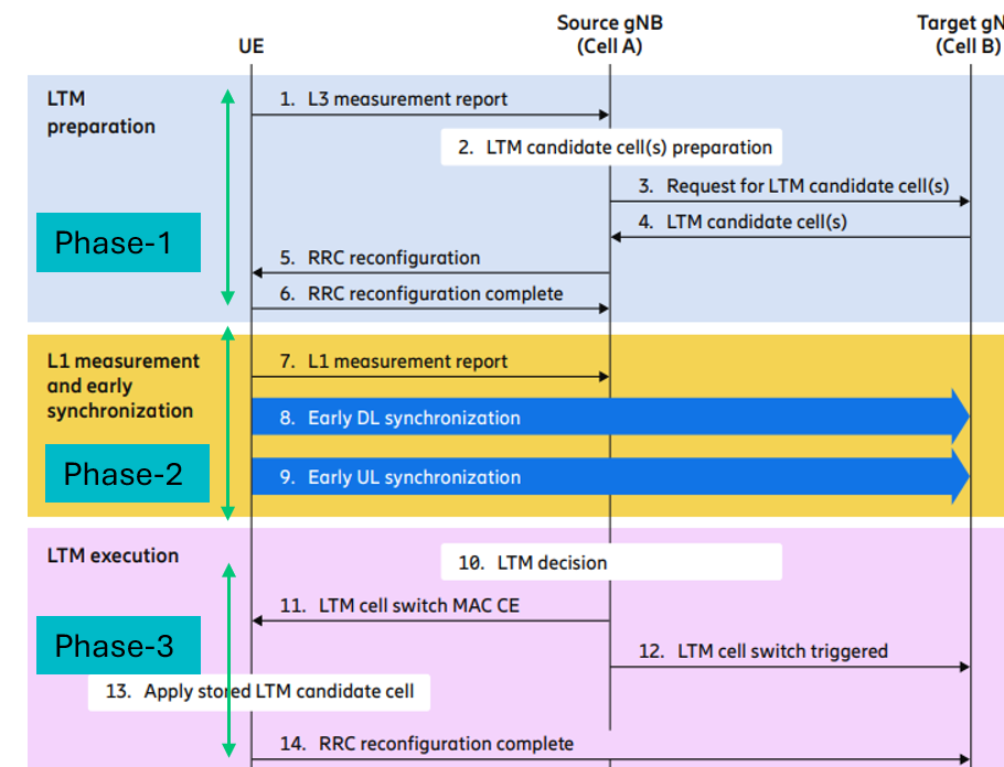
LTM Procedure (Key Phases - Illustrated in Figure below):
1.LTM Preparation (Steps 1-6): •UE receives configurations for one or more LTM candidate cells.
2. L1 Measurement and Early Synchronization (Steps 7-9): •UE uses configurations for L1 measurement and pre-synchronizes with candidate cells. Early DL Synchronization: UE determines DL receive timing of candidate cells.
Early UL Synchronization: Network determines Timing Advance (TA) of candidate cells.
3.LTM Execution (Steps 10-14): •UE performs the LTM cell switch to a selected candidate cell.

Member discussion