By Umer Aftab Rana 17 min read

5G Networking Modes

5G Networking Modes
Share:

1 Purpose

This document addresses the following questions regarding 5G Non-Standalone (NSA) and Standalone (SA) network architecture:

  • How are Option 4 series architectures classified within the NSA/SA framework, and why is this a common source of confusion?
  • Why is Option 3x the preferred choice among the Option 3 series architectures?
  • What are the key advantages of SA networking over NSA networking?
  • Why do operators and vendors recommend a phased NSA-to-SA migration strategy rather than direct SA deployment?

2 Overview

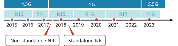
To accelerate the provisioning of 5G network services, 3GPP specifications have defined two 5G networking modes: Standalone (SA) and Non-Standalone (NSA). NSA specifications were frozen approximately six months prior to SA.

Figure 2-1 Evolution in 3GPP specifications

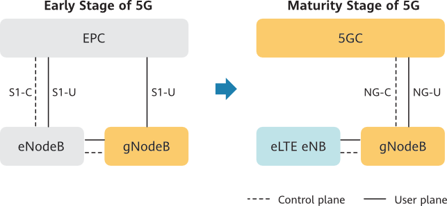
During the early stage of 5G deployment, 5G base stations — referred to as gNodeBs (gNBs) as defined in 3GPP specifications — can be connected to a 4G core network, referred to as the Evolved Packet Core (EPC). As 5G matures, the EPC connected to 5G base stations evolves into a 5G Core network (5GC), also referred to as the Next Generation Core (NGC) in certain protocol contexts. Ultimately, 5G base stations connect directly to the 5GC, enabling support for the full range of 5G use cases.

During network evolution, 4G base stations, referred to as eNodeBs (eNBs) can be upgraded to evolved LTE (eLTE) base stations, known as eLTE eNBs, enabling connectivity to the 5GC, as illustrated in Figure 2-2. This upgrade path extends the operational lifespan of existing eNodeB infrastructure and safeguards prior network investments.

Figure 2-2 5G network evolution


3 How to Distinguish Between NSA Networking and SA Networking

Figure 3-1 shows the mainstream 5G network architectures defined in 3GPP specifications, categorized as either NSA (Non-Standalone) or SA (Standalone) networking. The distinction is based on the number of radio access technologies (RATs) involved: architectures using two RATs are classified as NSA, while those using a single RAT are classified as SA.

NSA architectures differ in their choice of signaling anchor (control plane anchor):

  • LTE-anchored NSA: The gNB relies on an eNB or ng-eNB as the signaling anchor to provide 5G NR services. Option 3 series (Option 3/3x/3a) and Option 7 series (Option 7/7x/7a) fall into this category, with Option 3 connecting to EPC and Option 7 connecting to 5GC.
  • NR-anchored NSA: The ng-eNB relies on a gNB as the signaling anchor to provide LTE services. Option 4 series (Option 4/4a) belongs to this category.

Option 2 represents the SA NR architecture, where the gNB connects solely to the 5G Core (5GC) with no LTE anchor dependency.

Figure 3-1 Mainstream 5G network architectures

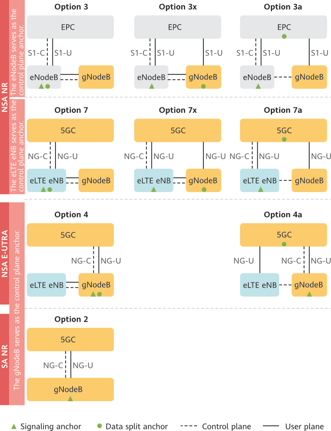
For an architecture with 'x', such as Option 3x, different base stations serve as the signaling anchor and the user plane (data) split point. For an architecture with 'a', such as Option 3a, the secondary node connects directly to the core network for its user plane traffic, bypassing the master node for data.

4 NSA Networking

NSA networking includes Option 3 series, Option 7 series, and Option 4 series architectures defined in 3GPP specifications. They apply to different stages of 5G network development.

4.1 Option 3 Series Architectures with NSA NR

At the early stage of 5G network deployment, the primary objective is to deliver 5G services by leveraging existing 4G infrastructure in a fast and cost-effective manner. To address this requirement, the 3GPP specifications define the Option 3 series architectures. In these architectures, the 4G Evolved Packet Core (EPC) is retained as the core network, while 5G base stations (gNBs) are connected to the existing 4G LTE radio access network. This approach enables operators to deploy 5G capabilities at reduced costs and with accelerated timelines. The Option 3 series comprises three variants ,Option 3, Option 3x, and Option 3a — each differing in the choice of network element (NE) that serves as the data split anchor point, as illustrated in Figure 4-1.

Figure 4-1 Option 3 series architectures
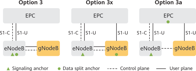
Option 3

In Option 3 (EN-DC), the eNodeB serves as the Master Node (MN), anchoring the control plane for 5G UEs operating in dual connectivity. In the base Option 3 configuration, all user-plane data from the EPC is routed through the eNodeB, which may then forward a portion to the gNodeB (Secondary Node) via the X2 interface for transmission to the UE. However, the Option 3 family includes sub-variants: in Option 3A, the EPC can send certain bearers directly to the gNodeB, bypassing the eNodeB on the user plane; in Option 3X, the gNodeB acts as the PDCP anchor for split bearers, receiving data directly from the EPC and optionally forwarding some traffic to the eNodeB., as shown in Figure 4-2.

Figure 4-2 Option 3

5G services require larger bandwidths and higher data rates than 4G services. However, existing eNodeB hardware cannot meet the data transmission requirements of 5G services. To address this limitation, the eNodeB hardware would need to be upgraded and the 4G network reconstructed under Option 3x. This significantly increases network construction costs for operators. Given these considerations, Option 3 is generally not the preferred choice for NSA (Non-Standalone) networking deployments.

Option 3x

In Option 3x, the gNodeB is the data split anchor. It carries all 5G user plane data or distributes some data to the eNodeB, as shown in Figure 4-3.

Figure 4-3 Option 3x

In Option 3x, eNodeB hardware upgrades are not required to achieve larger bandwidths and higher data rates for 5G services, and the amount of work involved in 4G network reconstruction is significantly reduced. 5G air-interface service data is transmitted directly to the Core network (EPC) through the gNodeB, bypassing the eNodeB user-plane bottleneck. The large 5G air-interface bandwidth guarantees efficient data transmission, maximizing bandwidth utilization.

In Option 3, all distributed service data must pass through the eNodeB. The eNodeB's hardware capability constrains the volume of service data over the S1-U interface, thereby limiting the data offloaded to the gNodeB. As a result, the large 5G air-interface bandwidth cannot be fully utilized.

Furthermore, in Option 3x, the gNodeB can detect radio signal changes in real time and promptly adjust the volume of service data to be distributed, ensuring a consistent user experience for 5G services. This dynamic adjustment is not readily achievable in Option 3a.

“Option 3x is the recommended architecture for NSA (Non-Standalone) networking.”

Option 3a

In Option 3a, the EPC is the data split anchor, as shown in Figure 4-4.

Figure 4-4 Option 3a

The EPC is connected to a radio access network (RAN) through S1 interfaces. It has no direct connection over the air interface, and therefore cannot detect in real time the radio condition changes on the RAN side. As a result, the EPC cannot dynamically adjust the amount of service data to be distributed based on the real-time radio condition changes. UEs are highly mobile. When they are moving, the radio condition continuously changes. However, the EPC cannot detect these changes in real time. It distributes 5G service data to the eNodeB and gNodeB based on the preset configurations (such as 4G and 5G cell capabilities). This causes user experience to deteriorate in the following two scenarios: When the 5G radio signal quality is good, the EPC does not increase the amount of data distributed to the gNodeB; when the 5G radio signal quality is poor, the EPC does not reduce the amount of data distributed to the gNodeB, causing a large number of packets to be lost. Therefore, Option 3a is not recommended for NSA networking.

In Option 3a NSA architecture, the EPC connects to the Radio Access Network (RAN) via the S1-U interface for user plane traffic and the S1-MME interface for control plane signaling. The EPC has no visibility into the air interface and therefore cannot detect real-time radio condition changes on the RAN side.

In Option 3a specifically, user plane data is routed from the EPC to the master eNB (MeNB), which then splits and forwards a portion of the traffic to the secondary gNB (SgNB) over the X2 interface. This split is governed by semi-static bearer configurations such as pre-provisioned QoS profiles and cell capability parameters, rather than real-time radio feedback. Because the EPC lacks a dynamic, closed-loop mechanism to monitor NR link quality, it cannot adaptively adjust the volume of data distributed across the LTE and NR legs in response to changing radio conditions.

UEs are highly mobile, and radio conditions on the NR leg change continuously. This static distribution logic leads to degraded user experience in two key scenarios:

  • When 5G (NR) signal quality is strong, the EPC does not increase the proportion of data steered toward the gNB, leaving available NR capacity underutilized.
  • When 5G (NR) signal quality degrades, the EPC does not reduce the data load on the gNB, resulting in increased packet loss and throughput degradation.

Because Option 3a relies on this static, non-adaptive traffic distribution mechanism with no real-time RAN feedback loop into the core, it is not recommended for NSA deployments where dynamic load balancing and consistent user experience are priorities.

4.2 Option 7 Series Architectures with NSA NR

At the mid-term stage of 5G network construction, 4G and 5G networks coexist. Following the Option 3 series architectures, the Option 7 series architectures defined in 3GPP specifications represent the next step in the evolution to 5G. To evolve to Option 7 series architectures, the 4G core network (EPC) in Option 3 series architectures must be upgraded to a 5G Core (5GC), and the eNodeB upgraded to an eLTE eNB for interfacing with the 5GC. The Option 7 series architectures include Option 7, Option 7a, and Option 7x. , as shown in Figure 4-5.

Figure 4-5 Option 7 series architectures


In Option 7 series architectures, the signaling anchor and data split anchor for the gNodeB are similar to those in their counterpart Option 3 series architectures. So similarly, Option 7x is recommended when an Option 7 series architecture is required during the evolution to 5G.

4.3 Option 4 Series Architectures with NSA E-UTRA

Option 4 series architectures are mainly intended for the phase when 5G NR coverage is already dominant and operators seek to maximize the utilization of existing LTE infrastructure. In these architectures, the eNodeB can be upgraded to an eLTE eNB  for interconnection with the 5G Core (5GC) via the NG interface, maximizing eNodeB utilization.

In Option 4 series architectures, the gNB serves as the master node (MN), handling RRC and NAS signaling toward the UE. This is different from Option 7 series architectures, where the eLTE eNB is the master node. From the perspective of the gNB, Option 4 series architectures are similar to the Option 2 architecture in SA networking described later in Section 5 (SA Networking).

“From the perspective of the eLTE eNB, Option 4 series architectures belong to NSA networking towards 4G because the gNB serves as the master node for UE access, making the eLTE-eNB the secondary node.”

Specifically, they employ NR-E-UTRA Dual Connectivity (NE-DC), with NR as master and E-UTRA as secondary. Option 4 series architectures include Option 4 and Option 4a, as shown in Figure 4-6.

Figure 4-6 Option 4 series architectures

In Option 4, the eLTE eNB provides the 4G air-interface bandwidth, supporting data transmission for access services. All user-plane data transmitted to or from the 5GC needs to pass through the gNodeB. Such an architecture does not require eLTE eNB hardware upgrades or reconstruction and fully utilizes the good coverage of the eLTE eNB.

In Option 4a, the eLTE eNB provides the 4G air-interface bandwidth and directly exchanges data with the 5GC. Such an architecture has a similar problem to that in Option 3a: The 5GC, as the data split anchor, cannot detect the real-time radio condition changes on the RAN side. Based on the preceding analysis, 

Option 4 is recommended when an Option 4 series architecture is required during evolution to 5G SA networking.

The preceding sections have elaborated on the classification of NSA networking. For a better understanding, this section briefly describes the concepts related to NSA networking, with Figure 4-7 as an example. In this example, dual connectivity (DC) is provided for the NSA UE, with two component carriers (CCs) aggregated on the eNodeB side and two CCs aggregated on the gNodeB side. Cells 1 and 3 are co-coverage cells, and cells 2 and 4 are co-coverage cells. Each cell corresponds to a carrier. The NSA UE must be capable of DC. That is, it can be connected to both the eNodeB and gNodeB.

Figure 4-7 NSA networking

Concepts related to NSA networking are as follows:

  • DC: An NSA DC UE is connected to both an LTE base station and a 5G base station. Signals are transmitted using radio resources from both of them.
  • MeNB: The master eNodeB (MeNB) is a base station that serves the cell on which the NSA DC UE is currently camping. In Figure 4-7, the eNodeB is configured as the master base station. In Option 7 series architectures, an eLTE eNB is configured as the master base station.
  • SgNB: The secondary gNodeB (SgNB) is a base station that provides a data split bearer for the NSA DC UE. In Figure 4-7, the gNodeB is configured as the secondary base station.
  • MCG: The master cell group (MCG) of the NSA DC UE is an LTE cell group configured on the LTE side. In Figure 4-7, cells 1 and 3 form the MCG.
  • SCG: The secondary cell group (SCG) of the NSA DC UE is an NR cell group configured on the NR side. In Figure 4-7, cells 2 and 4 form the SCG.
  • PCell: The primary cell (PCell) of the NSA DC UE is a cell that is served by the MeNB and that the UE is camping on. In Figure 4-7, cell 1 is the PCell.
  • PSCell: The primary secondary cell (PSCell) of the NSA DC UE is a primary cell that is served by the SgNB. The PSCell stays active once successfully configured. In Figure 4-7, cell 2 is the PSCell.
  • SCell: A secondary cell (SCell) of the NSA DC UE is a cell served by the MeNB or SgNB and configured for the UE through an RRC connection message sent by the MeNB. This cell can provide the UE with additional radio resources. In Figure 4-7, cells 3 and 4 are SCells. The PUCCH is available in each PCell and PSCell but not available in any SCell.
  • PCC: The primary component carrier (PCC) is the primary carrier of the MeNB and the carrier of the PCell. In Figure 4-7, the carrier of cell 1 is the PCC.
  • PSCC: The primary secondary component carrier (PSCC) is the primary carrier of the SgNB and the carrier of the PSCell. In Figure 4-7, the carrier of cell 2 is the PSCC.
  • SCC: A secondary component carrier (SCC) is a secondary carrier of the MeNB or SgNB. In Figure 4-7, the carriers of cells 3 and 4 are SCCs.

5 SA Networking

SA networking involves only one RAT. It includes the Option 1, Option 2, Option 5, and Option 6 architectures defined in 3GPP specifications.

Because the Option 1 and Option 5 architectures do not involve gNodeBs, and the Option 6 architecture has been abandoned as defined by 3GPP specifications, they are not covered here.

Option 2 Architecture with SA NR

Option 2 is a real 5G network architecture consisting of a new 5GC, gNodeBs, and 5G UEs. In Option 2, a gNodeB is directly connected to the 5GC through NG interfaces, eliminating the dependency on LTE networks, as shown in Figure 5-1.

Figure 5-1 Option 2

The 5GC is significantly different from the EPC, particularly in that it adopts a Service-Based Architecture (SBA), as shown in Figure 5-2.

Figure 5-2 SBA of the 5G core network


The SBA of the 5GC is based on the service- or microservice-based architecture paradigm established in modern IT systems. Each core network network element (NE) is implemented as a cloud-native module, with network functions (NFs) modularized to achieve functional decoupling and seamless integration. This modularization enables independent capacity scaling, autonomous evolution, and on-demand deployment of individual NFs without cascading dependencies.

All NEs on the control plane communicate with each other via Service-Based Interfaces (SBIs) over a common service bus, replacing the rigid point-to-point interface model used in 4G EPC. Unlike 4G, where a dedicated interface had to be defined for every NF-pair interaction, a single NF service can now be discovered and invoked by multiple authorized NFs dynamically. This approach enables all NFs to be instantiated, configured, and scaled on demand, providing the flexibility required to support diverse 5G service scenarios such as eMBB, URLLC, and mMTC.

The 5G Core (5GC) introduces a strict separation between the Control Plane (CP) and User Plane (UP) — a design principle formalized as CUPS (Control and User Plane Separation). The Session Management Function (SMF) is deployed centrally, typically within a core data center, to handle session establishment, modification, and release. The User Plane Function (UPF), by contrast, is deployed in a distributed fashion — closer to the network edge or end-user equipment (UE) — to minimize round-trip latency and offload traffic aggregation from the core. This architectural split reduces end-to-end latency, alleviates backhaul congestion, and strengthens security by isolating user data traffic from signaling flows.

The 5GC also natively supports network slicing, a capability defined in 3GPP Release 15 and beyond, which enables a single physical network infrastructure to be partitioned into multiple isolated virtual logical networks — each tailored to specific service requirements (e.g., eMBB, URLLC, mMTC). Each slice maintains its own independent Network Function (NF) configuration, QoS policies, and resource allocation. This elasticity allows operators to dynamically scale network resources on demand, significantly improve end-user experience per vertical, and enable new business models built around customized, SLA-driven service delivery.

Table 5-1 describes the main NEs involved in Figure 5-2.

Table 5-1 Introduction of NEs in SBA

NE

Major Function

AMF

Access and mobility management function. It has functions such as registration management, connection management, and mobility management. Through the AMF, the SMF and UEs exchange session management messages and UEs are authenticated upon access. The AMF indirectly participates in session management and forwards the UE session management signaling to the SMF. The AMF inherits the mobility management, registration management, and connection management functions of the 4G mobility management entity (MME), but not the MME's session management function.

SMF

Session management function. It has functions such as UE IP address allocation, UPF selection, and charging and QoS policy control. When there is downlink data on the peer network, the SMF notifies the AMF. Then paging is initiated. The SMF functions as the SGW-C, PGW-C, and the session management function of the MME in 4G.

UPF

User plane function. It has functions such as packet routing and forwarding of user plane data, traffic-based charging data record (CDR) generation, and data-plane anchoring. It functions as the SGW-U and PGW-U in 4G.

UDM

Unified data management. It manages subscription data and generates authentication parameters. It functions as the HSS in 4G.

AUSF

Authentication server function. It provides authentication for 3GPP and non-3GPP accesses. It functions as a 3GPP AAA server on an upgraded 4G network.

PCF

Policy control function. It provides charging policy management and QoS policy management. It functions as the policy and charging rules function (PCRF) in 4G.

NEF

Network exposure function. It exposes NF capabilities and services, and converts internal and external information. It functions as the Service Capability Exposure Function (SCEF) in 4G.

NSSF

Network slice selection function. It is a new NF in 5G that determines network slicing services for a UE based on the NSSAI or S-NSSAI provided by the UE and then determines which AMF provides access for the UE. Slicing enables 5G networks to meet the requirements of different application scenarios. Each slice corresponds to a series of customized network functions.

NRF

Network repository function. It provides registration and discovery functions. It enables the NFs to discover and communicate with each other over the application programming interface (API).

AF

Application function. It indicates various services at the application layer, including operator and third-party applications.

DN

Data network. It indicates an external data network such as the Internet.

(R)AN

Radio access network

UE

User equipment

6 NSA and SA Hybrid Networking

At the early stage of 5G network deployment, vertical industries and the ecosystem are not completely developed. Considering this, most operators with existing 4G networks use Option 3 series architectures. They build 5G base stations on 4G networks and gradually evolve the 5G base stations to SA networking. This process involves three types of 5G UEs. Table 6-1 describes the networking they support.

Table 6-1 5G networking modes supported by 5G UEs

UE Type

NSA Networking

SA Networking

NSA-only UE

Supported

Not supported

NSA and SA dual-mode UE

Supported

Supported

SA-only UE

Not supported

Supported

NSA-only UEs do not support SA operation. If the network evolves directly from NSA to SA, these UEs will experience service access failures due to incompatibility with the SA core network (5GC). To ensure a seamless transition for NSA-only UEs, a hybrid NSA/SA networking mode is introduced as an interim bridge between the two deployment architectures, as illustrated in Figure 6-1. The evolution path must therefore follow a phased approach: from NSA, to NSA/SA hybrid networking, and finally to standalone SA networking.

Figure 6-1 NSA and SA hybrid networking

Logically, NSA and SA hybrid networking consists of two networks that share 5G base stations. It requires that cells served by the base stations support both NSA and SA, and allows UEs in different modes to perform different services after access. For example, NSA UEs access an NSA network to perform 5G NSA services, while NSA and SA dual-mode UEs and SA UEs access an SA network to perform 5G SA services.

“Logically, NSA and SA hybrid networking consists of two co-existing network architectures that share 5G radio access infrastructure (gNBs). It requires that the base stations support both NSA and SA operational modes, and allows UEs with different capability profiles to perform different services upon access. For example, NSA-only UEs connect to the NSA network anchored by an LTE eNB (via dual connectivity with EN-DC) to perform 5G NSA services, while NSA/SA dual-mode UEs and SA-only UEs connect directly to the SA network (with a 5G NR core, i.e., 5GC) to perform 5G SA services.”

7- 5G Networking Evolution Paths

Option 2 is the ultimate architecture of 5G network development, therefore how can NSA and SA network architectures defined in 3GPP specifications be evolved to this ultimate architecture? The following are five common evolution paths. Operators can select the most appropriate path based on their existing networks.

  • Path 1: Direct deployment of Option 2
  • Path 2: Option 3 series > Option 7 series > Option 4 series > Option 2
  • Path 3: Option 3 series > Option 7 series > Option 2
  • Path 4: Option 3 series > Option 4 series > Option 2
  • Path 5: Option 3 series > Option 3 series and Option 2 hybrid architecture > Option 2

Path 1 is suitable for operators without 4G networks. Following this path, they can directly deploy 5G networks supporting all use cases including eMBB, URLLC, and mMTC. However, this path has high requirements on continuous 5G NR coverage and leads to high network construction costs.

Paths 2, 3, 4, and 5 are suitable for operators with existing 4G networks. They can select a path based on the type of UEs they serve. As described in 6 NSA and SA Hybrid Networking, paths 2, 3, and 4 do not support a smooth evolution to 5G SA networking for NSA UEs. 

“vendors recommend path 5. Successful cases from multiple operators have proven that the path with NSA and SA hybrid networking as an interim architecture ensures a smooth evolution for NSA UEs without wasting the investments of operators.”

8 References

  1. 3GPP TR 38.801, Radio access architecture and interfaces (Release 14)